
外观
GPIO 中断示例
概述
本文介绍如何在 睿擎工业开发平台 中创建并运行 GPIO 中断 示例工程。通过配置一个输出引脚模拟信号,并为输入引脚挂载中断服务函数(ISR),演示了系统如何捕捉引脚电平变化并实时触发响应。
GPIO 子系统
GPIO(通用输入输出)子系统是 RT-Thread 管理芯片引脚的核心框架。除了基础的电平读写外,它还支持“中断模式”,允许引脚在检测到特定电平变化(如上升沿或下降沿)时,自动触发预先设定的函数,从而实现对硬件事件的实时响应,无需 CPU 持续轮询。
GPIO 中断简介
中断(Interrupt)是实时操作系统中处理外部异步信号的高效机制。当外部硬件事件(如按键触发、传感器状态变更等)发生时,处理器会暂停当前任务,转而执行预设的中断服务程序(ISR),从而实现对实时事件的快速响应,无需通过循环轮询来检测硬件状态,极大地降低了 CPU 的占用率。
通过中断获取 GPIO 的输入电平信号
本示例演示如何通过 GPIO 边沿触发中断来捕获电平信号。我们将使用两个 GPIO 引脚:一个作为“输出模式”模拟电平跳变,另一个作为“中断输入模式”捕获电平跳变并触发中断回调函数。
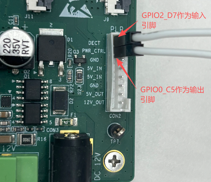
引脚连接
为保证代码与实际操作一致,本示例在 TL3576-EVM 开发板上,请使用杜邦线将 GPIO2_D7(即 95 号引脚,作为输入端)与 GPIO0_C5(即 21 号引脚,作为输出端)连接起来:
构建与烧录
创建工程点击展开


构建工程点击展开

固件下载点击展开


核心示例代码
GPIO 示例相关 API 说明
rt_pin_attach_irq:设置 GPIO 的中断模式,并且绑定中断触发回调函数rt_pin_irq_enable:使能 GPIO 中断rt_pin_detach_irq:取消 GPIO 中断的绑定rt_pin_irq_enable:失能 GPIO 中断
static void _gpio_isr(void *args)// gpio 中断回调函数
{
    rt_base_t pin = (rt_base_t)args;
    rt_kprintf("[IRQ] Detected on Pin ID %ld, Level: %d\n", (long)pin,
               rt_pin_read(pin));
}

static void _usage(const char *func_name)
{
    rt_kprintf("usage: %s <output_pin> <input_pin>\n", func_name);
    rt_kprintf("       %s -h\n", func_name);
    rt_kprintf("\n");
    rt_kprintf("output_pin    Output pin (e.g: p0.21)\n");
    rt_kprintf("input_pin     Input pin (e.g: p2.31)\n");
    rt_kprintf("\n");
}

int gpio_input_int_example(int argc, char *argv[])
{
    if (argc < 3 || strcmp(argv[1], "-h") == 0)
    {
        _usage(__func__);
        return 0;
    }

    rt_base_t out_pin = rt_pin_get(argv[1]);
    rt_base_t in_pin = rt_pin_get(argv[2]);
    rt_uint32_t count = 10;

    if (out_pin < 0 || in_pin < 0)
    {
        rt_kprintf("Error: Invalid pin names!\n");
        return -1;
    }

    rt_pin_mode(out_pin, PIN_MODE_OUTPUT);// 设置21号引脚为输出模式
    rt_pin_mode(in_pin, PIN_MODE_INPUT_PULLUP);// 设置95号引脚为上拉输入模式

    if (rt_pin_attach_irq(in_pin, PIN_IRQ_MODE_RISING_FALLING, _gpio_isr,
                          (void *)in_pin) == RT_EOK)
    {
        rt_pin_irq_enable(in_pin, PIN_IRQ_ENABLE);// 使能中断

        while (count--)
        {
            rt_pin_write(out_pin, PIN_HIGH);
            rt_thread_mdelay(500);
            rt_pin_write(out_pin, PIN_LOW);
            rt_thread_mdelay(500);
        }

        rt_pin_irq_enable(in_pin, PIN_IRQ_DISABLE);
        rt_pin_detach_irq(in_pin);// 取消 95 号引脚的中断绑定
        rt_kprintf("Test finished and IRQ detached.\n");
    }

    return 0;
}
运行示例
操作步骤
- 将 GPIO2_D7(作为输入脚) 与 GPIO0_C5(作为输出脚) 通过杜邦线连接
- 将工程编译完成后的程序下载到开发板中
- 打开串口终端工具,与开发板建立连接
- 在终端命令行中输入 gpio_input_int_example P0.21 P2.31 并回车运行
预期结果
- 开发板运行程序后,然后在终端输入
gpio_input_int_example命令 - GPIO 输出引脚每隔 0.5 秒转换 1 次电平,输入引脚会检测电平的变化
- 然后触发 GPIO 中断,在中断回调函数中会打印出当前电平
msh />gpio_input_int_example p0.21 p2.31
p0.21 --> gpio0.21 --> gpio0.C5
p2.31 --> gpio2.31 --> gpio2.D7
[IRQ] Detected on Pin ID 95, Level: 1
[IRQ] Detected on Pin ID 95, Level: 0
[IRQ] Detected on Pin ID 95, Level: 1
[IRQ] Detected on Pin ID 95, Level: 0
[IRQ] Detected on Pin ID 95, Level: 1
[IRQ] Detected on Pin ID 95, Level: 0
[IRQ] Detected on Pin ID 95, Level: 1
[IRQ] Detected on Pin ID 95, Level: 0
[IRQ] Detected on Pin ID 95, Level: 1
[IRQ] Detected on Pin ID 95, Level: 0
[IRQ] Detected on Pin ID 95, Level: 1
[IRQ] Detected on Pin ID 95, Level: 0
[IRQ] Detected on Pin ID 95, Level: 1
[IRQ] Detected on Pin ID 95, Level: 0
[IRQ] Detected on Pin ID 95, Level: 1
[IRQ] Detected on Pin ID 95, Level: 0
[IRQ] Detected on Pin ID 95, Level: 1
[IRQ] Detected on Pin ID 95, Level: 0
[IRQ] Detected on Pin ID 95, Level: 1
[IRQ] Detected on Pin ID 95, Level: 0
Test finished and IRQ detached.